

Parallel computer giving light show
Parallel computing in Basic
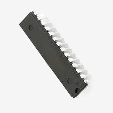
Micromite PIC32MX170F256
Geoff Graham made a very nice Basic firmware for the PIC32MX170F256 series microcontrollers called MMbasic. This is an easy to understand programming language with a lot of features and power. The 28 pins PIC32MX170F256 is a very cheap microcontroller. For between €3 – €4 a piece (depending on how much you order) it’s very good value for money. This together with MMbasic and the fact that you only need a few external components it is easy to start with programming right away.
In my opinion it’s much easier to learn to program MMbasic then it is to program an Arduino. I always had a soft spot for the Basic language because my first computer was a Sinclair ZX81. I learned a lot from it while programming it in Basic although the ZX81 was not very fast and the Basic interpreter was very limited. MMbasic on the other hand has a lot of features and is much more powerful then the good old ZX81 Basic and even beter MMbasic is much much faster! And even greater it’s FREE for everyone to download and use for whatever you want to. You can read more about MMbasic and how to program the PIC32MX170F256 with the firmware on the website of the creator of this fine Basic firmware at http://geoffg.net/micromite.html
So when I was experimenting with the Micromite II I thought why not make a kind of parallel computer with a few seperate slave nodes. All nodes with their own PIC32MX170F256 and working with MMbasic. Yes I know this can sound as a stupid idea because each 28 pins PIC32MX170F256 only works on max 48 Mhz. If you really want a fast parallel computer this is not the way to do it. But on the other hand MMbasic is really easy to understand and to program, so you could learn a lot about parallel processes and have a lot of fun on the way learning. Even if it is slow you can still do some interesting things with a slow parallel computer.
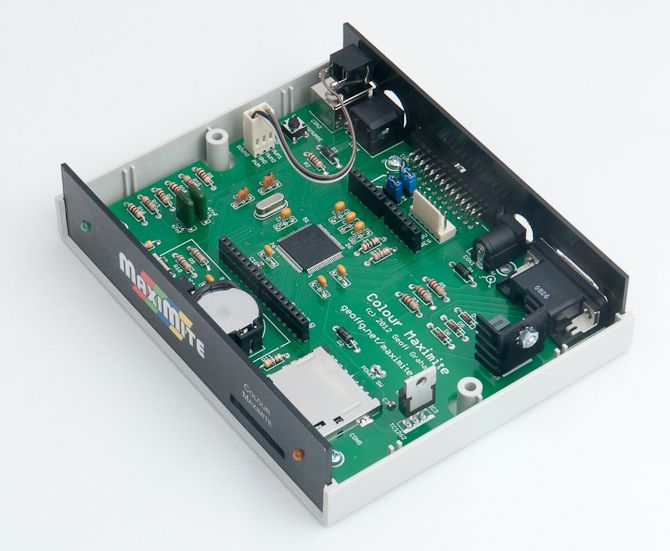
Maximite colour computer
I began a test setup with 4 nodes as slaves and one Maximite computer as a Master to experiment with the idea of parallel computing. As a means of communication between them I used the I2C protocol. That’s why there are slaves and a master. For those who don’t know about the Maximite computer just check Geoff Grahams page for more information. The Colour Maximite uses the same (but more extensive) MMbasic language and also offers a VGA output among other things. It’s the big brother of the Micromite. With the Maximite I was able to show the results of the slaves on a monitor screen. The hardware part was easy to setup but then I needed some program to experiment with. I needed a program with a lot of calculations and found a Fractal program for MMbasic from Loki from the Backshed forum which I integrated in the testprogram for parallel computing. The Maximite computer was setup as a master for the I2C communication and the 4 nodes as slaves. Each slave node has it’s own address which it can read by itself because I hardwired it on 7 pins (remember I want to expand to 80 slave nodes so I need 7 bits to decode an address between 8 and 87). With this I can use the exact same program for all the nodes. At the start of the program the slave nodes look at the pins and calculate their own unique address and so know who they are if the master is calling 🙂 . The I2C protocol allows for 128 seperate addresses in 7 bit mode but some addresses are reserved so the useable addresses are a bit less then 128.
The Maximite computer plots the calculated pixels which it receives from the nodes. Each node calculates a part of the screen coördinates. So if the Y axis has 432 pixels and you use 4 nodes each node calculates 108 horizontal pixel lines for the Maxite screen. At the start of the program the maximite asks how many nodes must do a calculations and with which variables and sends this to the nodes. So if you enter the number 2 only 2 nodes start calculating and the job is split automaticly to 216 pixels each. In other words the slaves do all the calculations and the master only plots the fractal according to the information received back from the nodes. See for a full understanding the example code for the master and slave right here.

prototype parallel computer with 4 nodes
If you look at the code it looks all simple but at the start I had a lot of problems with the I2C protocol timing. Therefore I had to build in some delay’s which slows the parallel computing a bit 🙂 but on the other hand with 4 nodes the fractal was drawn on screen almost 3.5 times faster then with only one node (speed gain is also depending from the calculting depth of the fractal image and the used variables). And after some fiddling I got the setup working foolproof. Now I had a working 4 nodes parallel computer but why stop there? Why not make a bigger one just for fun. If it works with 4 nodes it should also work with much more nodes.
On the left you see the prototype setup of some boards I made earlier on for micromite experiments. The layout was different and not useable for what I wanted. Furthermore I had only ten of them made so not enough for more nodes. Maybe you are surprised to see a batteryholder for 2 x AA mignon batteries but the Micromites are not power hungry. The 4 nodes worked fine for a long time on just 2 AA batteries.
First of all I had to make another professional PCB if I wanted to scale up. So I designed a new 10cm x 5cm PCB in Kicad with a sea of holes and a double pin connection to each PIC32MX170F256 pin. I also placed an RGB LED because with a RGB LED you can monitor each node with 8 different states depending on color and on/off state, and it can give a nice light show 😉 . I could have made the PCB much smaller but I wanted to have a flexible design that I could also use for other purposes and with a sea of holes I could always add sensors or switches or whatever I come up with in the future. If you want you can download the gerber files right here. I orderd my PCB’s at www.itead.cc as long as you keep the PCB’s 10cm x 5cm or smaller they are really cheap. But you have to be patient before you get the finished product in your hands. I live in the Netherlands and it takes 3-4 weeks to arrive, most of the times. I ordered 100 PCB’s and planned to make a parallel computer with 80 nodes. 8 stacks of ten nodes each to make a total of 80 nodes.
Why 80 nodes you might ask? Well I had bought a nice Acrylic cube at Ikea called Synas with LED lighting from the bottom. I just bought it because I liked it but had no special purpose for it at the time. But when I looked at it again I thought why not build the Parrallel computer in this nice acrylic case? After some measuring I decided I could fit 80 slave nodes in it and so I decided on a parallel computer with 80 nodes. I also needed a good power supply. The Micromite doesn’t use that much power but if you connect 80 nodes and 80 LEDS it adds up so I bought a solid power supply which gives 3.3 volts with a maximum of 15 Amps.
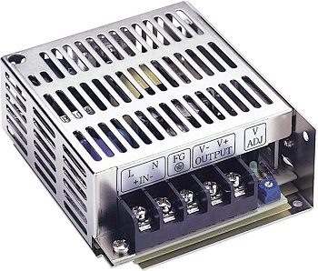
power supply 3.3 volts 15 Amps
The power supply was too big to put in that same acrylic case so I designed a wooden box and cut it out with my laser cutter and put a coat of paint on it. It fits exactly under the acrylic case and it gives more then enough room to fit a power supply and more if needed. If you want to make your own you can download the wooden base in Coral Draw format right here. So far the case for the computer units but most important are the PCB’s with the electronics. So now more explaining about these.
Soldering the PCB’s is not that difficult but it’s a lot of work if you have to do 80 PCB’s.
For each PCB you need:
- 1 x 28 pins IC socket
- PIC32MX170F256
- 1 RGB LED Common Cathode
- 1x 100nf Ceramic capacitor
- 1x 47uF tantal capacitor (must be a Tantal!)
- 3 x resistor 100 ohms
- wire bridge R1 resistor on PCB (made from cut of 100 ohm resistor)
You also need a seperate Maximite computer for the Master program, distance holders for between the PCB’s and some 3 pin headers for the RX/TX programming pins
When I received the PCB’s I noticed a stupid mistake (alway’s check and double check your PCB design before you send it out, yes I know 🙂 ). I forgot to include resistors for the RGB LED. But with some tinkering this was quickly solved. I have corrected this mistake in the gerber files so no problems for you 🙂 . Because I used 7 pins to hardwire the address and also needed 2 pins for the I2C connection there are seven I/O pins left for other future use. The free pins are 7, 9, 10, 16, 21, 22 and 23. More then enough for some nice experiments with parallel sensors or whatever you come up with.

Front of PCB micromite II
If you look at the PCB you see a R1 resistor this is only needed when you use the board for ICSP programming. For the parallel computer just make a wire bridge. The R2 an R3 resistors of 2k2 ohms are only needed on ONE board. This is to tie the i2C lines to +3.3 volts. If you do this at the Master Maximite computer you don’t have to use them at all just keep them empty. C2 is for the 47uF tantal capacitor and C1 for the 100nf ceramic capacitor. The 3 Resistors on the left of the LED are 100 Ohms.
After you soldered all the boards you need to place a sticker on each of them with the addresnumber for reference. Begin with address 8 and end with 87 for 80 nodes. Beginning at 8 because addresses 0 to 7 are reserved and not useable. After you have done this you can start hardwiring the address for each node according to the address sticker you made. You can use this table for it. For each 1 you connect it to the 3.3 volts and for each 0 (zero) you make no connection.
As address pins I used pin 5, 6, 14, 15 ,24, 25 and 26, seven bits in total. If you want to do this on different pins be my guest but don’t forget to change the “get-address” subroutine in the slave program if you do. You can use PINS 1, 13 and 28 for connecting to +3.3 volts and also the VCC holes on the PCB. See the addressing table for easy reference here.

Top of parallel computer nodes stack
As an example you see a slave node PCB with address 68 above this. The binary address for this node is 1000100. This means that pin 5 and pin 24 have to be connected to 3.3 volts to be 1. As you can see pin 1 (3.3Volts) is connected to pin 5 to pull it high and also pin 24 to pin 28 (also 3.3 volts). This PCB is the upper node on a stack of 10 PCB’s from address 68 to address 76. You don’t see the 3 x 100 ohm resistors for the LED here because this was the first batch of boards with the forgotten resistors :-). I soldered them on the copper side so they are there but you don’t see them. In the picture you also see a 3 pin header connected to GND/RX/TX. This is only connected to the uppermost node. I will explain later how to program 10 nodes in one go fast and easy. All the boards are spaced with 20mm spacers and connected with blank copper wire at the following points:
- GND
- VCC
- RX
- TX
- I2C DATA
- I2C Clock
Because I used blank copper wire between the nodes I took care to put them not next to each other. At the sides of the sea of holes (below and upper side) you see two 14 hole strips. These are a copy of the PIN connections next to the PIC IC. So you can connect the I2C Data line next to the PIC IC and the other I2C Clock line on pin 17 on the strip on the left below the sea of holes. So you have a nice seperation of the wires. You can do the same for the RX and TX lines. The GND and VCC lines are connected on the small strips on the left of the PIC IC.
 To the left you can see the stacking of the 10 nodes and the blank copper wire connecting the nodes. To make a parallel computer with 80 nodes you have to make 8 identical stacks and make sure you hardwire the addresses right. Before you stack the boards check them for shorts to be sure all is oke because after you stack them and soldered the copper wires it is not easy to change things. Although I used 20mm metal spacers for some moving room to repair things its more easy to do this if the boards are still seperated. And don’t forget to program MMbasic in the PICS before you insert them into the boards as explained on http://geoffg.net/micromite.html . Because otherwise there will be not much computing going on 🙂 . First stack the boards with the metal spacers, I used just two but if you want you can use four but this is not necessary. When this is done insert the copper wires and slide them in one go through the ten boards. Solder the copper wires to each board and cut of the exces wire from bottom and top. When this is done you have to program this stack with a small test program that flashes the leds with a frequency depending on the address of the node. How higher the address how slower the flashing. You can download this very simple test flashing program here. To program the nodes you need a USB to TTL serial convertor. Connect it to the GND, RX and TX pins at the connector at the top of the nodes and use Terraterm to transfer the program in one go to the 10 nodes. You do this with the following steps:
- Start Terraterm with a 34800 setting
- Copy the program code
- Type in Terraterm the command autosave to start all the 10 PICS waiting for the code
- Paste the program in terraterm
- Hit Ctrl+Z key to save it in the memory of the pics when the pasting is done
- Type run in Terraterm window
If this all worked you get a stack of flashing lights. If you take the power of and put it on again the program starts again because of the autorun option in the program. See the video Below for the light effect with 80 nodes :-).
Oke for now about the testing of the nodes. After the Micromite parallel cluster is finished you can load the master and slave code for the Maximite (master) and the micromites (slave nodes) into all of the computers. For the maximite just put the master program on a SD card and for the micromites use the same program technique as described before 10 nodes at the time. But remember because of the fact there is already a program running in the nodes (the test program) you have to add another step before step one and thats type CTRL/C to break the running program of flashing LEDS. If you don’t do this you cannot give the autosave command. If you feel lucky just try to program 20 or 30 nodes in one time sometimes this also works. If you use Terraterm, sometimes you get all giberish in the Terraterm window if you type someting in it. Most of the times you can ignore this and just do your thing and it programs al fine. If you don’t like the look of it just restart Terraterm and most of the times it shows readable characters again.

I2C input output for parallel computer
After you programmed all the computers you have to connect the I2C lines from the Maximite to the Micromite cluster. I have done this with a DIN connector as shown above here. Remember to also make a connection between the GND from the Maximite to the Micromite cluster otherwise it won’t communicate. So you connect GND to GND, I2C data to I2C date and I2C clock to I2C clock. Don’t forget to place one 2K2 ohms resistor on each I2C line (not the gnd line). You can do this at the side of the Maximite or on the first Micromite board on the PCB. After this power up the Micromite cluster and if all the nodes are working you will see a green light. This means it is waiting for variable information from the Master to start calculating.

Micromite computer cluster waiting for variable data from Master
Then you start up the master program on the Maximite and you will get the following screen:

The master computer asks for input
The first input asks for how many slaves you want to use (still in Dutch, I forgot the translation 🙂 ) for calculating a part of the fractal image. In this case I use 72 nodes and not 80 nodes. This is because the Maximite plots on 432 horizontal lines and 432/72=6 lines for each node. If I use 80 it would be 432/80=5.4 lines for each node. The calculations would go wrong and you will not get a right fractal image. You could change this by changing the program but it’s just a proof of concept to show how the cluster calculation is working. So for now just use an amount of cluster where 432/nodes= a whole number of lines.
Then you add some variables for the image you want and a max iteration of 100 or more as needed. Then hit the Enter key and each node in the Micromite cluster will receive the variables and start to calculate a part of the code and will send this back to the Master which will start plotting the image. You will see that all the 72 nodes you activated will have a red coloured LED at this state. This proving that the nodes received the variables and are now working on the calculations.

72 micromite nodes are active calculcating. The last 8 are inactive and stay green.
The screen of the master will show the fractal being plotted. You can see each part of the fractal being calculated by a different node.

72 nodes drawing each a part of the fractal image
If the fractal image will be finished the nodes will light a blue LED to show their part of the calculation is ready.

72 nodes have finished their task and signal the blue LED.
To start again just switch the Micromite cluster off and on again and you can calculate a new fractal. In the example below I used just 4 nodes. You can also use 1 node if you want to.

Parallel computing calculating 4 only nodes

Fractal image calculated with 4 parallel computer nodes
Now maybe you think that calculating the same fractal image with 80 nodes will be 80 times faster then with 1 node. But this is not true. At some stage the Maximite cannot plot any faster and also the communication between more nodes slows the proces down. It depends on what image you calculate, but most of the times 12 nodes is the optimum for plotting the fractal image. More nodes are even slower. So why build 80 nodes then you might ask. That’s because the fractal program is just a proof of concept to show the workings of a parallel computer. If you give each node a more time consuming calculation, 80 nodes will be fine and faster. It just depends on how you program the nodes and what kind of task it will do.
So I hope I gave you some inspiration to add some nice features to this parallel computer concept. Maybe with a much better program or maybe with a nice application which can be done with this parallel cluster. Just let me know and share what you have come up with. It will be nice to hear from you. For now have fun with the Micromite parallel cluster and learn from it. You can alway’s start with a small cluster of only ten Micromite nodes.
To finish this, below a badly made 🙂 video clip which shows the cluster in action.